Video: Youtube Video
Introduction
Today, we are going to explain how a computer converts electricity into numbers. We’re also going to briefly touch on the basics of how a computer can combine these different electrical signals to do operations involving boolean logic and even addition.
Prerequisites for understanding
The minimum necessary knowledge to understand the following is a rudimentary understanding of exponents, specifically exponents of 2.
It also helps to be familiar with Hertz as a unit for measuring frequency, though this is not strictly necessary.
Computers deal in electricity
At the most fundamental level, computers deal strictly with electricity. When dealing with electricity, a point in time can either be on or be off. Computer science refers to 1 as being on and 0 as being off. Each 1 or 0 is referred to as a bit of information. This is the smallest unit of information that a computer deals with. At the lowest level, you either a 0 bit or a 1 bit on a wire.
The most reductive way to explain what a computer does is that it observes and processes sequences of 1s and 0s. These bits then get converted and processed into instructions that allow the computer to achieve everything it is that you expect a computer to do. In fact, this explanation of what a computer does is where the turn of phrase “1s and 0s” comes from. The computer observes a sequence of four bits, like 1 1 0 1, and understands what it should do when it sees that sequence.

Part of what makes a computer work is being able to observe multiple sequences of bits at the same time and process them using logic gates. The simplest gates that computers deal with are NOT, OR, and AND gates. Often, a computer deals with many of these gates combined in different sequences to fulfill a desired operation, like adding two numbers together. However, this is a longer topic that won’t be covered here. For now, we are just going to focus on the basic gates and what they do.
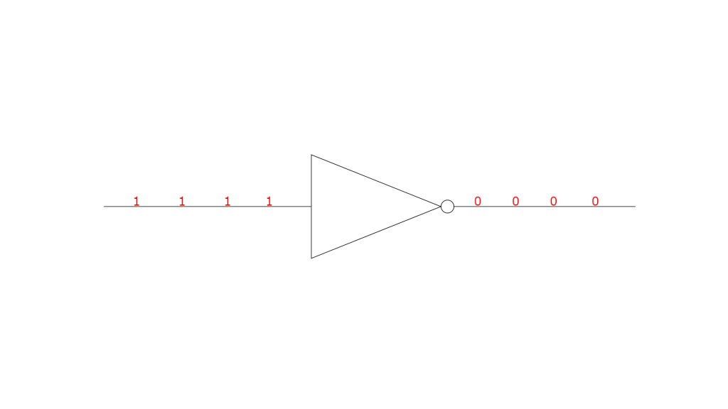
In a NOT gate, any bit that passes through gets inverted. This means that if a 1 goes through it becomes a 0 and if a 0 goes through, it becomes a 1.
An OR gate, takes several input bits and generates a single output bit (two or more wires in and one out). If any of the incoming wires have a 1 bit on them, then the output also has a 1 bit. Only if all incoming wires have 0 bits does the OR gate output a 0.

An AND gate also takes several inputs and generates a single output. However, the AND gate functions in the opposite way of the OR gate. AND gates need to have 1 bits on all inputs for the output to also have a 1 bit. Anything less than all 1s means that the AND gate will output a 0.


To reiterate, by using a combination of these gates we can combine different sequences of 1s and 0s to logically determine if something should happen. Additionally, we can interpret those sequences of 1s and 0s as numbers and then use a combination of these gates to add those numbers together. Logic gates, organized in one way or another, are the underpinning of almost all the operations that a computer executes.
Turning electricity into numbers
Sequences of bits only have a meaning in so far as we tell the computer to give them meaning. Take a sequence like 1 0 1 1. Technically, that sequence could mean anything. However, as computers developed, a standard was agreed on that allows for the conversion of that sequence into a number by using powers of 2. 2 is the standard because using a larger number would make it impossible to represent certain numbers. Why this is the case will become more clear after we go through a conversion example with the number 2.
As a special note, computer science starts counting a location in a sequence starting at 0. Typically, you might consider the person at the front of a line to be in 1st place, however, in computer science, that person would be in 0th place. The idea this represents is that you’ve progressed 0 places from the beginning of the line. And, since you are still at the beginning, and haven’t moved, your location count (also know as the index) is 0.
Another important note is that, when interpreting a sequence, we start the calculation by reading the sequence from right to left. In the sequence 1 0 1 1, we can see that there is a 1 in the 0th position, a 1 in the 1st position, 0 in the 2nd position, and 1 in the 3rd position.
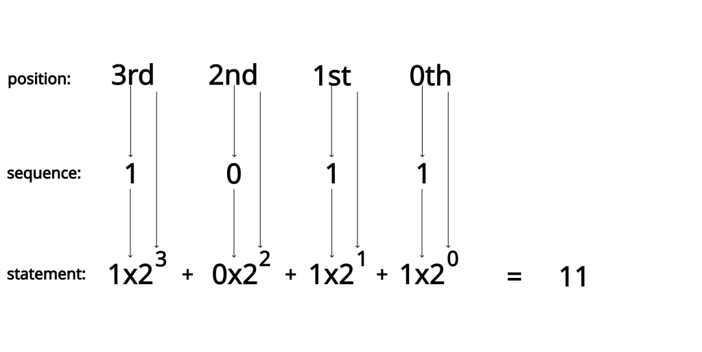
By using these index positions, the sequence can be converted into the following mathematical statement
Then, by evaluating this expression, we can determine that the sequence of 1 0 1 1 should represent the number 11. By doing this for bit sequences of arbitrary length, any integer can be represented this way.

We aren’t going to get into how we take care of negative numbers, or decimals (also sometimes referred to as floats) here, but know that there is another way of interpreting a sequence of 1s and 0s to get any number you might want to use in a calculation.
How does a sequence happen
Understanding the concept of clock rates is crucial when working at the level of 1s and 0s. In fact, the clock rate is what tells to computer to go and check and see if a 1 or a 0 is currently taking place. Without getting too into the weeds, electricity being on or off is considered a continuous event. Meanwhile, 1s and 0s occur at specific points in time. Take the following image as an example.
How many 1s exist in this picture? How many 0s? What sequence of 1s and 0s should we convert this in to? Do you think it should it look like this?
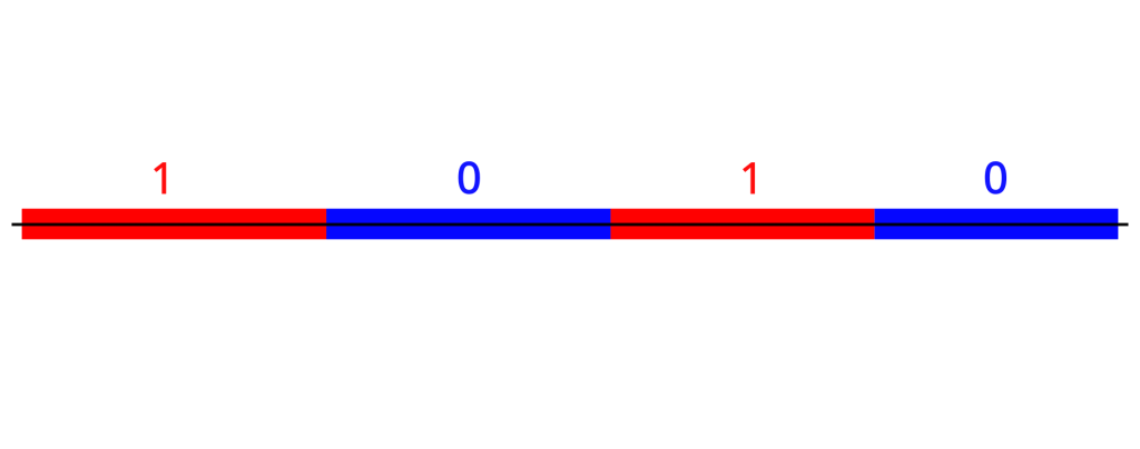
Maybe something like this.
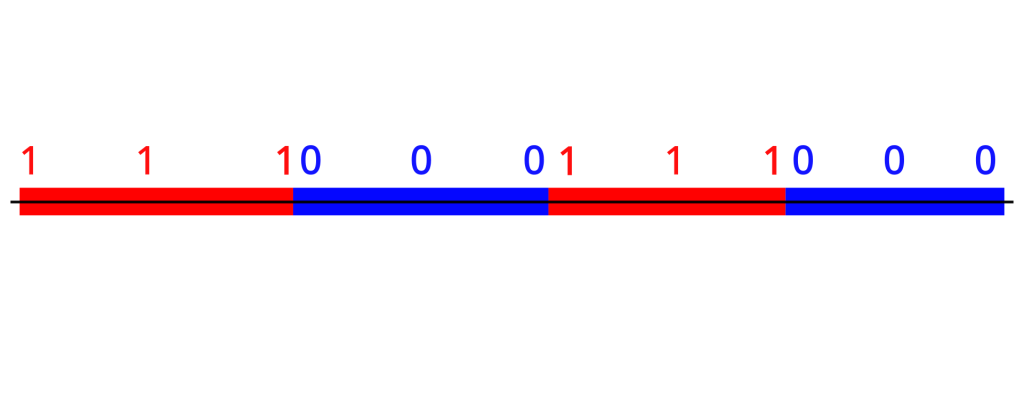
Or even something like this

The clock rate of the CPU determines which of the diagrams is correct. The faster the clock rate, the more bits you can interpret in a smaller amount of time. This means that you can process information faster the higher a clock rate you have. Though I won’t get into it here clock rate is determined by the quality of the components of the CPU as well as how long the slowest operation on the CPU takes to complete. Here is the Wikipedia article that explain clock rate and goes more in depth about its determinants.
Clock rate is measured in a unit called Hertz (often gigaHertz, which is a hertz * 10^9). The unit of Hertz is used to measure frequency, which works perfectly for us since we are measuring the frequency that our processor checks for 1s and 0s. To get more into specifics, a Hertz is an alias for the reciprocal of a second (s^-1). A fair analog to a reciprocal of a second, in English, is how many times does this event occur per second.This relationship between Hertz and seconds is also particularly convenient as it allows for the conversion between a, likely, more unfamiliar unit in Hertz to a near universal unit in seconds.
Right now, a modern Intel Core i9 CPU has a clock rate (or as Intel puts it max turbo frequency) of 5 gigaHertz. This means that one operation can occur in 1/(5 * 10^9) or .0000000002 seconds. When comparing the speed of processors, Hertz, however, is often preferable to clock speed in seconds. In addition to being a unit made to measure this exact sort of phenomenon, Hertz also follows the rule of bigger number means better. This is particularly important since, when shopping for CPUs, clock rate isn’t common knowledge, however, the bigger number being better definitely is, which makes it easier for purchasers to make a more informed decision.
Using multiple wires to make a sequence
Representing a sequence using a single wire, while useful for initially teaching about bits, is ultimately misleading without further explanation. In the real world, there are multiple wires that are interpreted at the same time, instead of just one wire being interpreted over multiple clock cycles. The addition of more wires allows for signaling to be faster.
To illustrate this point, let’s generate the binary sequence for 9 using one wire and using 4 wires. With a single wire, you would need to wait for 4 clock cycles to generate the binary sequence of 1 0 0 1, which represents 9.

However, by having 4 wires and processing them all at the same time, the computer only needs one clock cycle to generate the 9 sequence.
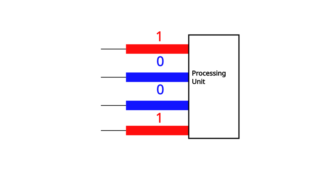
This 4 wire machine would be called a 4 bit architecture, meaning that the largest amount of information that can be transferred inside a processing unit is 4 bits per clock cycle. People that use computers and download software are likely more familiar with 32 bit and 64 bit architectures, as that is what is most commonly found on modern machines. In fact, both modern versions of Windows and Mac OS are built to run on 64 bit architectures, which is why you might see them listed as Windows 64 bit or Mac OS 64 bit. In addition, any software that runs on these operating systems also has to be prepared with the underling architecture in mind for it to run properly on your machine.
With all that being said, it isn’t uncommon for architectures and diagrams of processing units to use singular wires when representing a sequence. For example, it might be common to see a diagram like this.
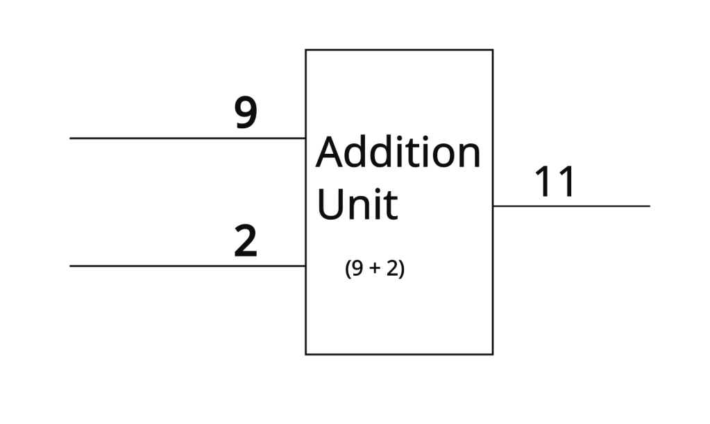
Single wires are a convenient short-hand when drawing these sorts of diagrams. If this diagram is of a 32-bit machine, you could technically zoom into that wire that has the 9 on it and see that it’s actually 32 wires just really close together with the sequence 00000000000000000000000000001001 on them. As you might imagine, this is a headache to read and write, so people deal with the abbreviated version instead. All this is to say, don’t get confused if you see a single wire with a number on it, this wire is just a whole bunch of wires in disguise for the sake of convenience.

Thanks
Thank you so much for reading this post. I hope I was able to teach you something today. Well, that’s all for now, I hope that you have an amazing rest of your day.

Leave a comment